release time:2024/07/22
The technical indicators of motors are largely related to their manufacturing materials and manufacturing processes. In motor manufacturers, the quality of products made from the same design structure and the same batch of raw materials often varies greatly. Without advanced manufacturing process technology, it is difficult to produce advanced products.
The geometric tolerances of each processing surface should comply with the requirements of the drawings. Among them, the coaxiality of the two end stoppers and the inner circle, and the jump of the two end faces to the axis centerline of the stoppers are the key to machine base processing. The inner circle and the iron core should have appropriate tightness to ensure that the stator iron core does not loosen or move during the operation of the motor.
For motors with feet, the plane of the feet should be parallel to the axis centerline. The distance between the foot hole and the centerline of the machine base should be symmetrical and meet the specified tolerance.
The rigidity of the end cover structure, the dimensional accuracy of the stoppers and the bearing chamber, and the geometric deviation will affect the uniformity of the air gap between the stator and the rotor.
The main shaft is usually made of 45 high-quality carbon structural steel or 40Cr alloy steel. The spindle processing is divided into two stages: preparatory processing and forming processing. Preparatory processing is round steel straightening, blank blanking, flat end face and center hole drilling. Forming processing is rough turning, semi-finishing turning, grinding outer circle, milling keyway, etc.
The core gear diameter, bearing gear diameter and roughness of the shaft, the outer diameter size and roughness of the rotor core, the spacing of the bearing gears at both ends, and the coaxiality of the outer circle of the core and the shaft are all key to processing. The shaft and the core and the fan blade should be properly tight to ensure that the rotor core and the fan blade are not loose or strung during the operation of the motor. In addition, the shaft extension and keyway size tolerances should meet the requirements of the relevant product standards for installation size tolerances.
The surface of the punching sheet should be smooth and the thickness should be uniform. The burrs of the stator and rotor punching sheets are ≤0.05mm.
The coaxiality between the inner circle or center hole of the punching sheet and the outer circle: the inner and outer circles are punched once with Φ0.04 ~ 0.06mm, and the inner and outer circles are punched twice with appropriate width.
The unevenness of the distribution of the slot teeth of the punching sheet, that is, the difference between the maximum and minimum tooth width is 3 or 4 levels.
The center line of the slot should pass through the center of the circle and should not be obviously skewed.
The insulation layer on the surface of the punching sheet should be thin and uniform, and have sufficient dielectric, oil-resistant and moisture-proof properties.
The number of punching sheets with missing edges shall not exceed 2%, and the height of the missing edges shall not exceed 20% of the height of the yoke.
The task of the core pressing is to align and press a certain number of punching sheets to fix them into a whole with accurate size, neat appearance, and appropriate tightness.
The weight or stacking coefficient of the core must comply with the requirements of the drawing. Insufficient core weight will increase the magnetic induction intensity, resulting in increased iron loss of the motor, increased excitation current, and reduced power factor and efficiency.
The pressure should be uniform and the tightness should be appropriate. The core should not be loose or deformed under the combined effects of mechanical vibration, electromagnetic and thermal forces. If the core is too loose, the number of punching sheets in a certain length will be reduced, which will not only result in insufficient magnetic cross-section, but also cause vibration noise and damage insulation; if it is pressed too tightly, the insulation resistance between sheets will be reduced, or even damage the insulation between sheets, which will increase the iron loss sharply. Uneven pressure will easily damage the insulation at over-tight places, and over-loose places will often cause the core to loosen.
Shape requirements. The coaxiality of the core should be within the specified range, and the punching sheets should not appear wavy after pressing. The edges of the core, especially the teeth, should not be raised.
The axial centerline position of the core should meet the specified requirements to ensure the symmetry of the stator and rotor centers.
The insulation between the core sheets should not be damaged.
There should be no cracks on the end rings, fan blades and balance columns.
The size and depth of the shrinkage holes on the surface of the end rings should be less than 20% of the height of the end rings, with a maximum of no more than 3mm, and only one hole is allowed at each end.
The blade and corner defects should be less than 3mm.
The allowable deviation of the rotor slot slope is ±1.0mm.
The bevel line of the rotor outer surface must be straight, and the rotor misalignment should generally be less than 0.5mm from the slot bevel line.
Check for defects such as broken bars, cracks, pores, looseness and shrinkage.
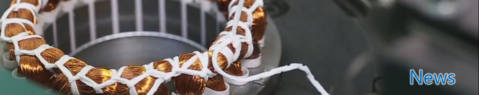
The winding is a key component of the motor and the most vulnerable link. It is affected by electromagnetic, thermal, mechanical vibration, and environmental factors. The life of the motor and the operating reliability mainly depend on the winding.
The diameter and number of turns of the winding wire should be accurate. Each coil joint should not exceed one, each phase coil should not exceed two, and each unit should not exceed four. The joint must be at the end bevel, and the wrapping should comply with regulations.
The size is moderate and meets the requirements, which is guaranteed by the winding mold.
The coils should be arranged neatly, not crossed, and the insulation should not be damaged. The insulation between turns and to the ground of multi-turn coils should be good and reliable.
Before embedding, the core should be checked and cleaned. Any protrusions on the stator surface and in the slot should be filed and blown clean (not in the embedding area).
The winding pitch (slot pitch), coil-to-coil connection and lead-out wire relative position must be correct.
The winding slot insulation, layer insulation and phase-to-phase insulation should be good and reliable. The quality and structural dimensions of the insulation material should meet the requirements.
The surface of the slot wedge should be flat and smooth. The winding insulation should not be damaged during insertion. It should have appropriate tightness. The end should not be cracked and should not be higher than the inner circle of the core. The length of the winding, insulation and slot wedge exposed at both ends of the stator core should be symmetrical.
The wires at the end of the winding should be arranged neatly without serious crossing. The end binding and insulation should meet the requirements.
When embedding and shaping, metal tools should not be used to directly contact the winding, and excessive force should not be used to avoid damaging the insulation.
The lead-out wire joints should be welded firmly to ensure good contact, sufficient mechanical strength, smooth surface, and no desoldering or cold soldering. Splashes such as copper dust and welding slag should be strictly prevented from damaging the winding insulation and mixing into the winding.
The lead-out wires should be arranged neatly, of the same length and meet the requirements. The lead-out mark should be marked in the same specified position.
The slot bottom insulation should not be cracked, and the wire should not have insulation damage. If there is a crack in the slot, it must be padded with the same material as the slot insulation, but the total number of cracks shall not exceed 3, and the core shall not be broken.
The stator core with windings is not allowed to roll on the ground, and the coil insulation shall not be damaged during its stacking and transportation.
The varnish is uniform and transparent, free of impurities and blocky substances, and no deterioration. The viscosity of the varnish should meet the process requirements.
After drying, the paint film on the surface of the winding should be uniform in color, non-sticky and slightly elastic to the touch, with no cracks or wrinkles on the surface, no deformation at the end, no bumps or exposed copper on the copper wire, no separation of the lead wires, and no misalignment of the slot wedges.
Copyright © Ningbo Nide Mechanical Equipment Co., Ltd.


